Checking the washing machine triac
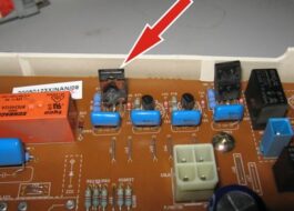
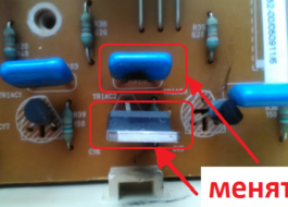
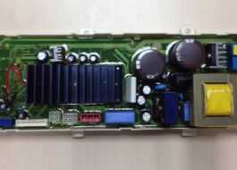
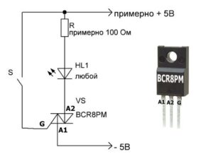 The control board of the washing machine is “strewn” with semiconductor devices - triacs. It happens that one or more elements burn out, and the machine can no longer perform its functions in the previous mode. It is quite difficult for the average person to visually identify burnt parts, so you will have to diagnose the module.
Of course, if possible, it is better to entrust electronics repair to specialists. If you want to check the triac in the washing machine yourself, you need to prepare properly - study all the nuances of the upcoming work. We'll tell you how semiconductors are tested.
How can I test the parts?
There are several ways to check the control board of an automatic machine. Technicians most often perform diagnostics on an electronic module using a multimeter, a transistor tester, or a special stand. At home, craftsmen sometimes test triacs using a regular light bulb and battery.
The most convenient and easiest way is to check the triac in a washing machine using a multimeter.
If you do not have this measuring device at home, you can buy it at any specialized store. The cost of multimeters is low - from $2-3 and above. An inexpensive model is also suitable for home use.
Triacs and their typical problems
To understand how to test triacs, you need to understand what the design features of these elements are. These are semiconductors that constantly open and close during operation. They ensure the flow of electric current in two directions.
If we talk about the design of a triac, it consists of two crystals directed towards each other and a control electrode. The latter ensures the opening and closing of the semiconductor. Due to this device, these elements are considered a type of thyristors.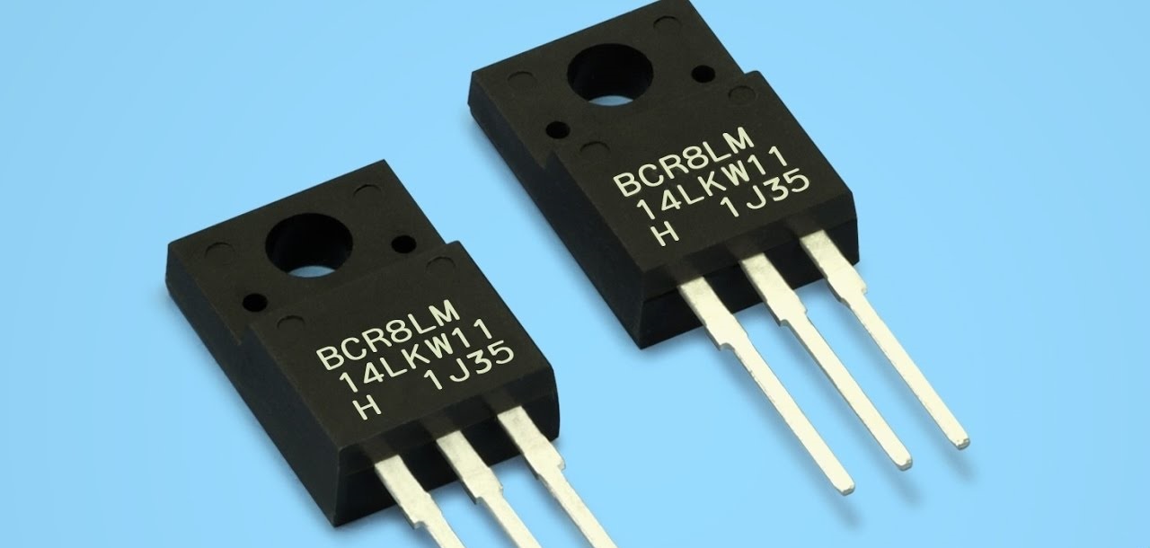
An open circuit may occur in the triac circuit, and the element may also burn out due to a short circuit. If you plan to test a semiconductor with a multimeter, you can do it in two ways:
- with desoldering of the triac;
- directly on the control board.
The second method is much more convenient, because it will be possible to check the semiconductor device without additional manipulations with radio components. However, the results of such diagnostics will also be affected by the overall performance of the electronic module. Therefore, it is advisable to test the triac by unsoldering it from the board - this way the accuracy of the study will be higher.
When checking on the board, a short circuit in a parallel branch can affect the results. In this situation, the multimeter will indicate a malfunction of the triac, while the problem will not be in this semiconductor device at all.
Test with separation of the triac from the board
The most accurate diagnostic results will be if you remove the triac from the control board and check it separately. If you test a part that is independent of anything, the multimeter will give more realistic readings. Having chosen this diagnostic method, you need to decide how the leads or “legs” of the semiconductor are located. There are several types of triacs, the image below shows only a few of them.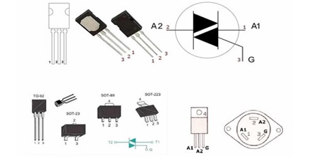
Be sure to determine the location of the triac control contact in relation to the pair of power terminals.
The contact layout should be known in advance. You can see which pin is which by looking at the model or the semiconductor datasheet. This is critical for further diagnosis.
The structure of semiconductor elements is similar. Any triac has 3 contacts - two power and one control. A pair of working pins is usually labeled A1 and A2 (sometimes T1 and T2). The remaining one is the English letter G.
Having understood the design of the triac, you can begin setting up the multimeter. The tester should be switched to the “dialing” mode. The vast majority of models of such devices have a separate button that needs to be turned on. The key is indicated by a symbol of a diode and a buzzer (simulating a sound signal).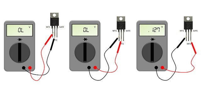
Having switched the multimeter to the “continuity” mode, attach its probes to the corresponding contacts of the triac. A potential difference will appear between the tester leads, as voltage will be applied to them. The device will ensure that the test current begins to “flow” through the semiconductor. Diagnostics of the control board element is carried out in several stages.
- Step 1. The multimeter probes are placed against the power contacts. If the device screen displays 1 or “OL,” it means the triac is working. A zero on the tester’s display will indicate that the semiconductor has “broken through.”
- Step 2. One multimeter probe remains on the working contact, the second is connected to the control terminal. Normally, the tester screen should display a value from 100 to 200 V, minor differences are allowed.
- Step 3. Make sure the triac opens. To do this, quickly touch the control electrode without ceasing to supply voltage to the operating terminals. The values on the multimeter display should change immediately.If the readings are corrected, then the semiconductor is working.
To connect the multimeter probes to two “legs” of the triac at once, you can use additional wiring.
If during the check of the soldered triac no violations are detected, then the reason is not in it, but in another semiconductor of the control board. You will have to continue the diagnostics and test all elements and tracks of the module one by one.
Interesting:
1 reader comment











Where to buy a washing machine control module?